Modelling a bicycle brake or derailleur cable terminal for 3D printing
Creating a simple model for 3D printing with OpenSCAD
We are going to perform a simple example of using 3D modeling techniques for subsequent 3D printing.We will manufacture a terminal for brake cable and / or change of bicycle.
For modeling we will use OpenSCAD, free software for the creation of 3D solid objects because it is free to use and also allows parametric design, so it will be possible to later modify the dimensions to adapt the model to each particular need.
OpenSCAD download link: https://openscad.org/
We begin by drawing up a sketch that represents our initial idea.
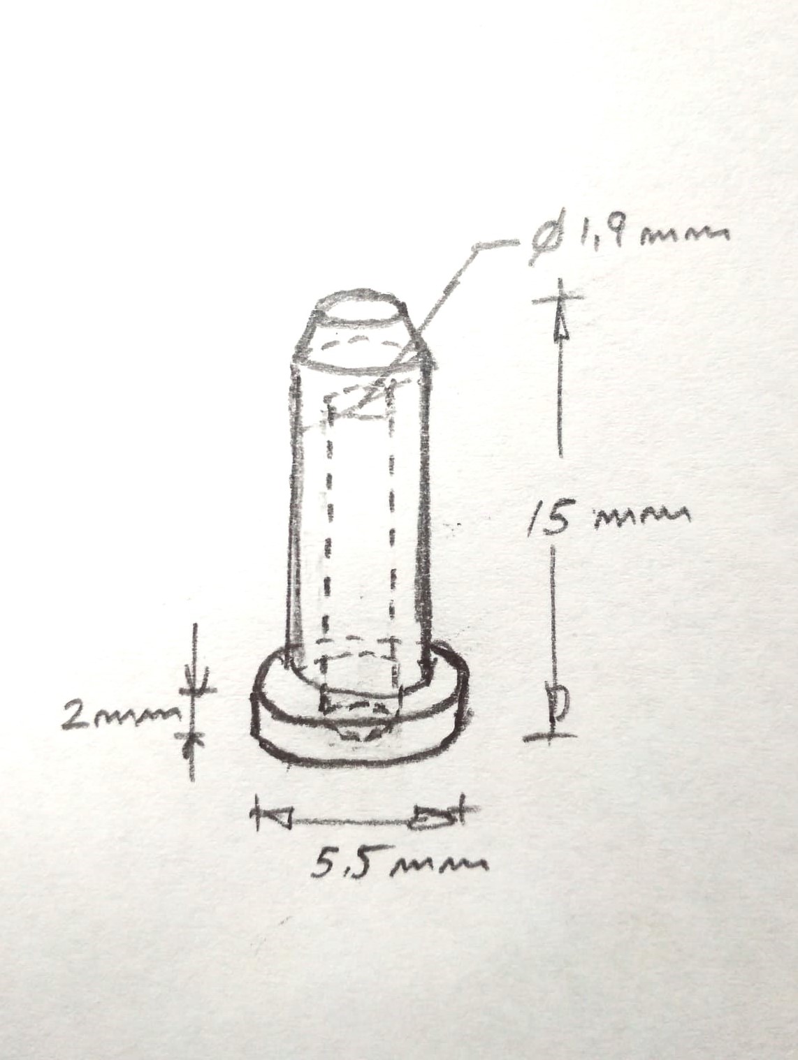
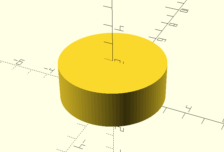
Already in openSCAD, let's start with the base drawing a cylinder of diameter 5.5 mm. and height of 2 mm.
cylinder(d=5.5, h=2, $fn=100);
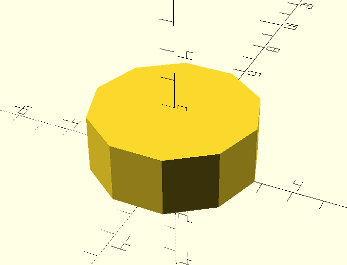
The variable parameter $fn is used to indicate the number of segments that will form the base circle of the figure and therefore the number of faces of the cylinder. This would be the result for a value $fn = 10
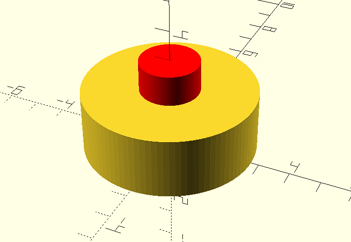
The bore will be another cylinder of the same or greater height and diameter of the bore:
cylinder(d=1.9, h=3, $fn=100);
In the following figure it is represented in red color and with a height of 3 mm. for better visualization.
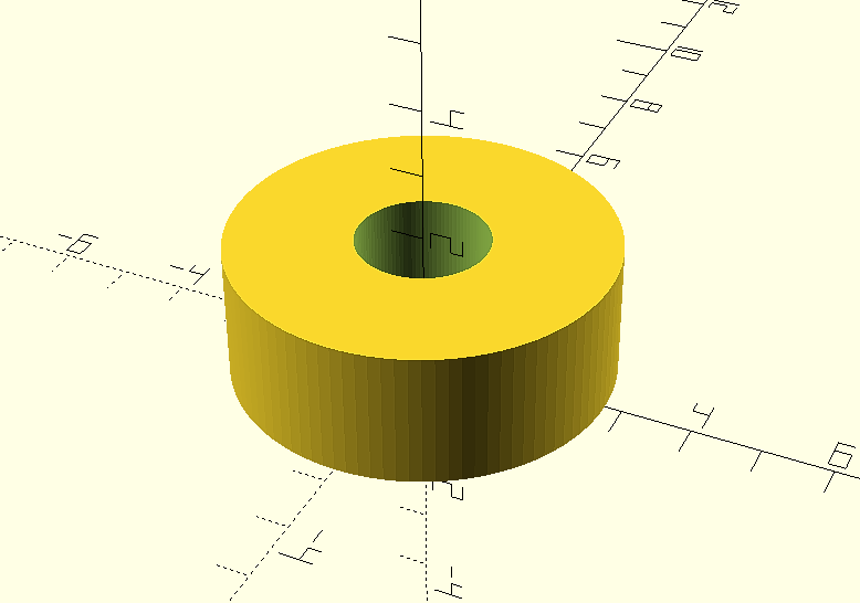
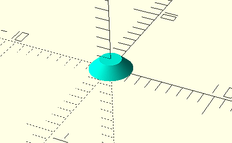
But now what we have are two overlapping cylinders, so that the second cylinder is the perforation of the first one we will use the modifier “difference()” that will make the difference between the first and second elements indicated:
difference(){
cylinder(d=5.5, h=2, $fn=100);
cylinder(d=1.9, h=3, $fn=100);
}
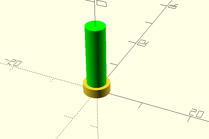
We are going to create the second cylinder or main body of the object, its diameter will be 4 mm. and its length will be 13 mm.
cylinder(d=4, h=13, $fn=1000);
To make its initial position coincide with the upper face of the base cylinder, we will move it 2 mm along the vertical axis "Z" using the transformation “translate ([x, y, z])”:
translate ([0, 0, 2])
cylinder(d=4, h=13, $fn=1000);
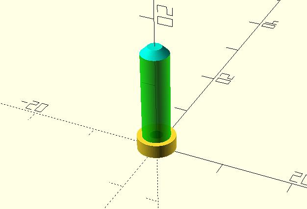
We will drill the hole as we saw before, although in this case we do not want it to go through its entire length, so its length will be less than 1 millimeter.
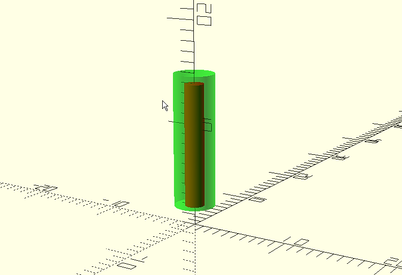
difference(){
translate([0,0,2]);
cylinder(d=4, h=13, $fn=1000);
cylinder(d=1.9, h=12, $fn=1000);
}
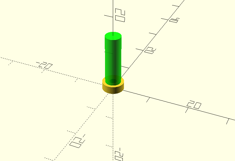
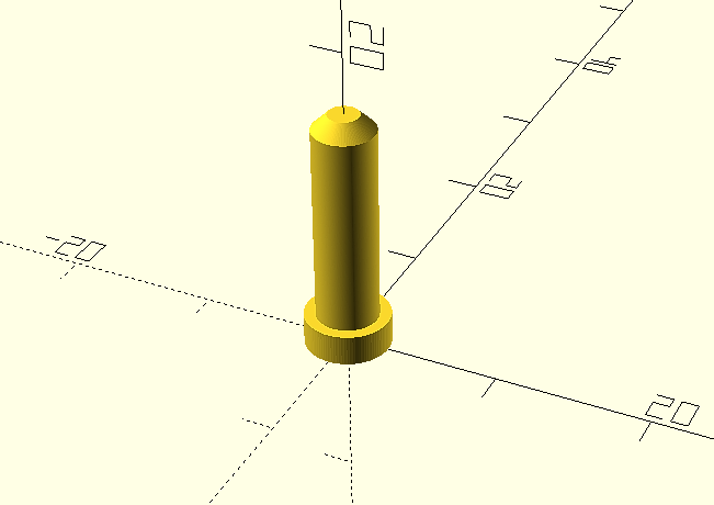
Now all that remains is the upper chamfering. In this case we will do it as a third element, again we will use a cylinder, but we will define a smaller diameter for the upper face. We will use again the primitive "cylinder" to create a cylinder of height h=1, lower diameter d1=4 and upper diameter d2 =2.
cylinder(h=1, d1=4, d2 = 2, $fn=100);
And again we move it to its correct position at the upper end of the terminal.
translate([0,0,15]);
cylinder(h=1, d1=4, d2 = 2, $fn=100);
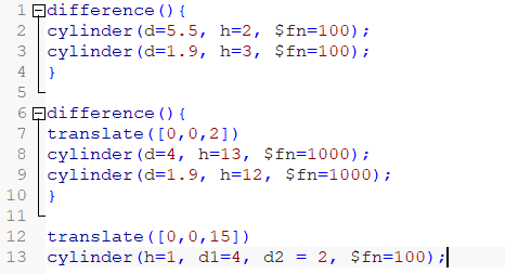
The final result, including the complete code will be:
difference(){
cylinder(d=5.5, h=2, $fn=100);
cylinder(d=1.9, h=3, $fn=100);
}
difference(){
translate([0,0,2])
cylinder(d=4, h=13, $fn=1000);
cylinder(d=1.9, h=12, $fn=1000);
}
translate([0,0,15])
cylinder(h=1, d1=4, d2 = 2, $fn=100);
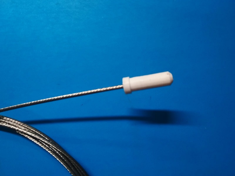
Then we will render it (F6) and export it for 3D printing, in our case in .STL format. And this will be the final result once printed.
Sicami Tracks - Inizio